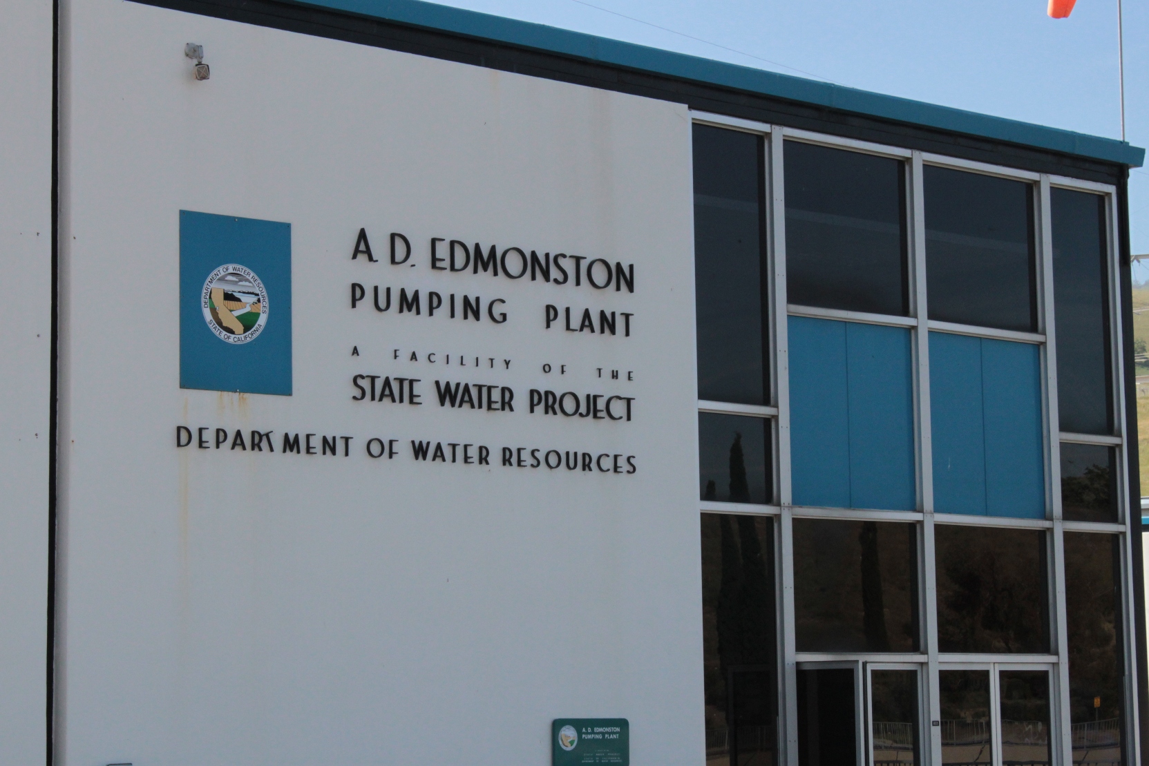
The pumps that lift the California Aqueduct over the Tehachapis form the highest single lift pumping plant in the world. In April of this year, I had the pleasure of touring the facility on a Metropolitan Water District Inspection Tour.
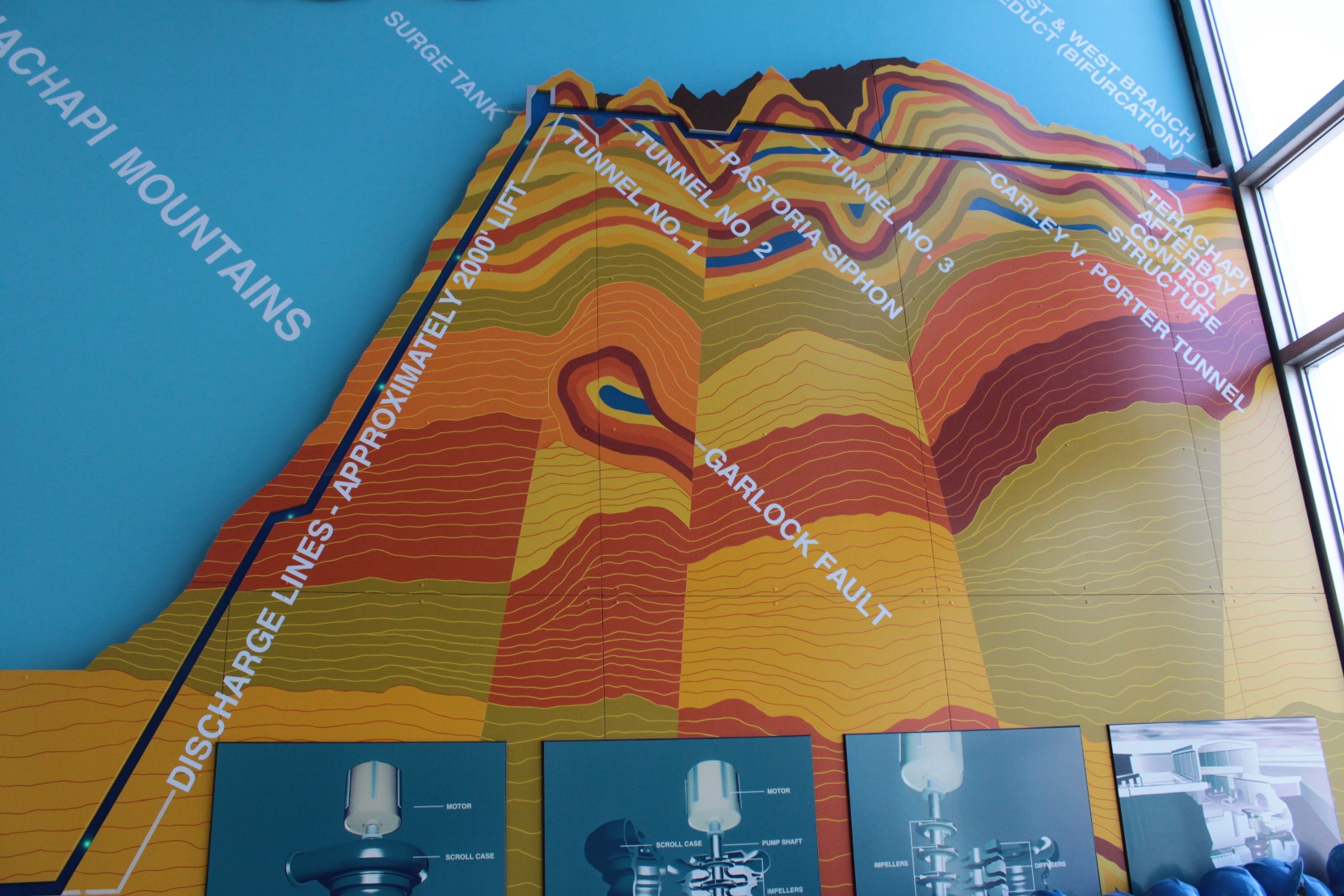
Inside the lobby of the building is a diagram depicting how the water is moved over the Tehachapis. The pumps push the water nearly 2000 feet up the mountain where a series of tunnels and pipelines takes it across the mountains. The crossing traverses or paralells several major faults, including the San Andreas fault, so rather than build a deeper and shorter tunnel, the decision was made to keep the aqueduct closer to the surface to facilitate repairs in the event of an earthquake.
There are 14 4-stage 80,000-horsepower centrifugal pumps that push the water up to the top of the mountain.
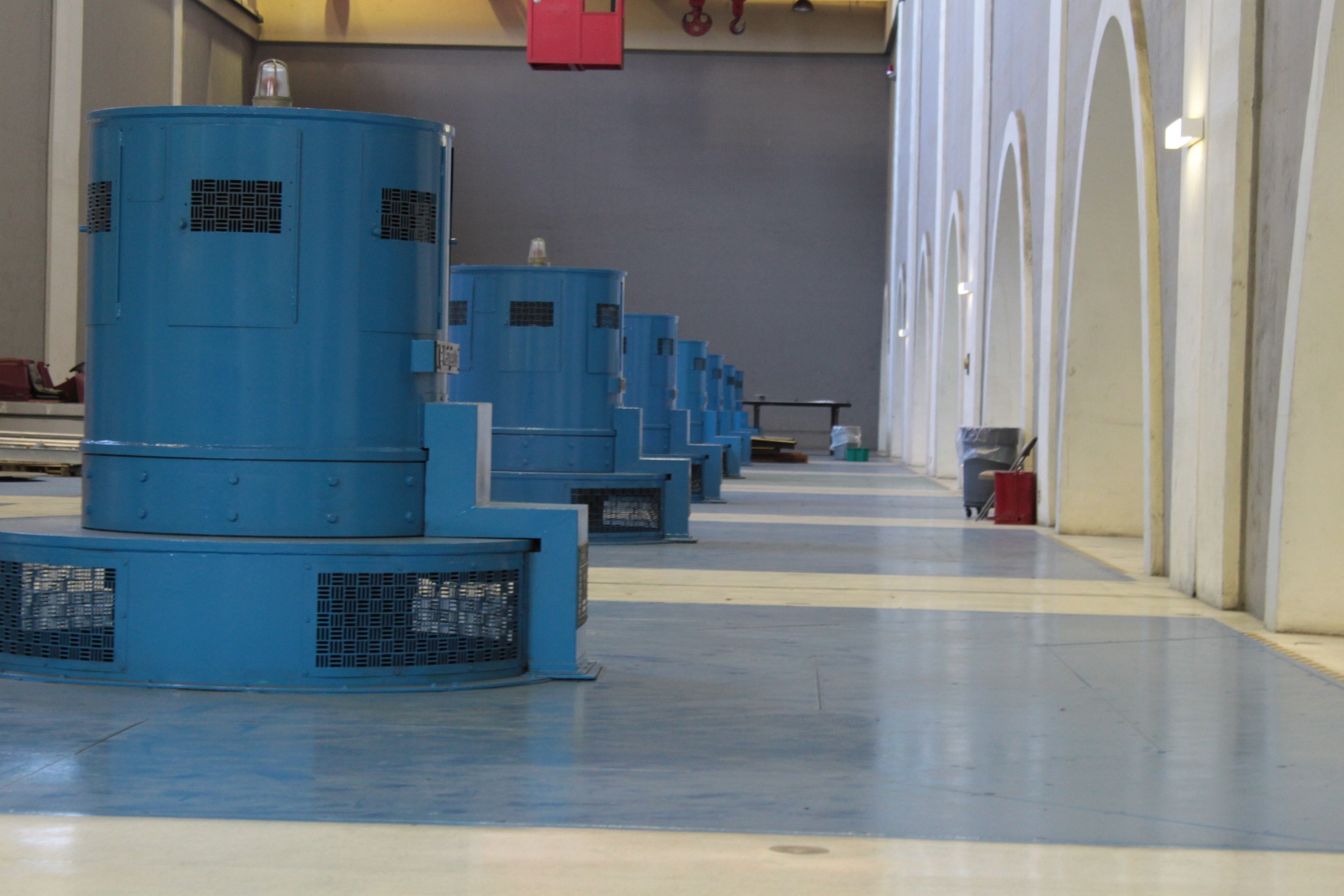
Each motor-pump unit stands 65-feet high and weighs 420 tons. This is a picture of the top of the pumps; the pumps themselves extend downward six floors.
Each unit discharges water into a manifold that connects to the main discharge lines.
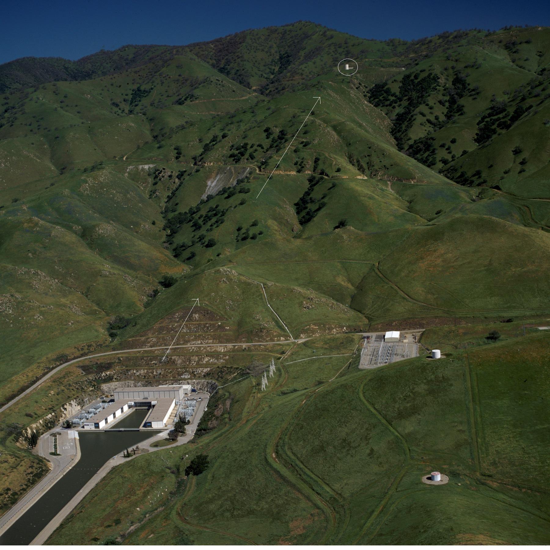
The two main discharge lines stair-step up the mountain in an 8400-foot long tunnel. They are 12.5 feet in diameter for the first half and 14-feet in diameter for the last half. They each contain 8.5 million gallons of water at all times. At full capacity, the pumps can fling nearly 2 million gallons per minute up over the Tehachapis.
At the top of mountain, there’s a 68-feet high, 50-foot diameter surge tank. This prevents tunnel damage when the valves to the pumps are suddenly open or closed. Near the top of the lift there are valves which can close the discharge lines to prevent backflow into the pumping plant below in event of a rupture. This picture is from the Department of Water Resources, but the lines drawn are mine. Notice that the pipelines are buried.
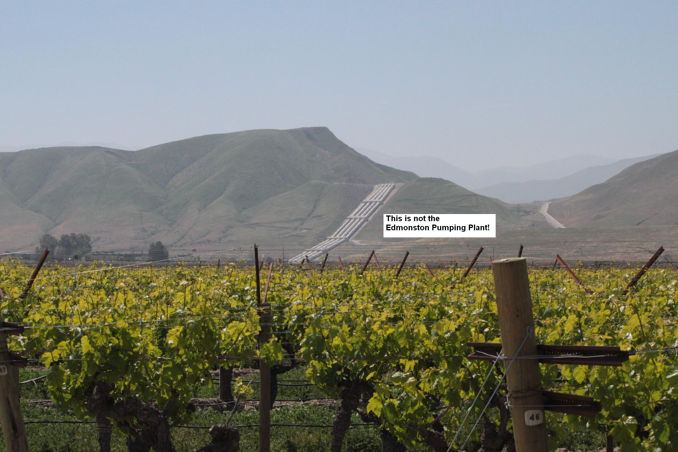
Let me take a moment to correct a common misconception…. Many people who travel the I-5 near the southern end of the San Joaquin Valley confuse the Chrisman Wind Gap facility (pictured below) for the Edmonston facility. The Chrisman Wind Gap facility, while certainly more visually impressive, only lifts the water 800 feet up; the lift at Edmonston is more than twice as high.
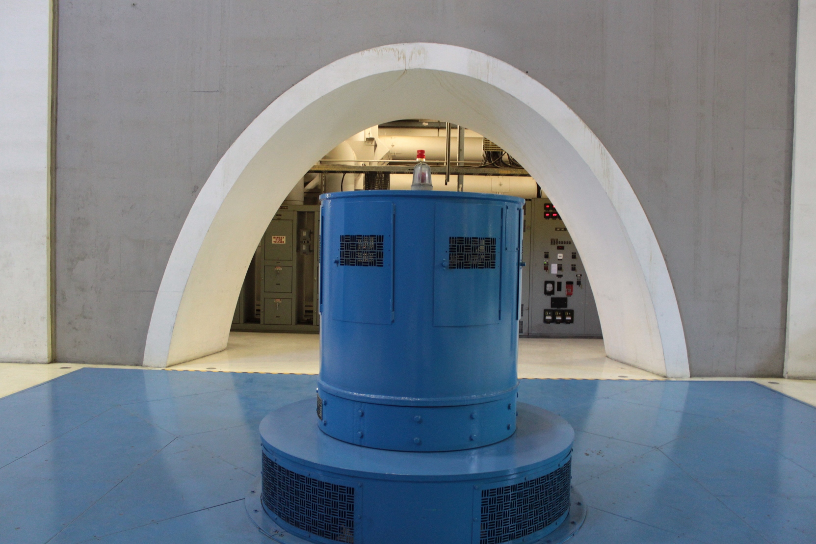
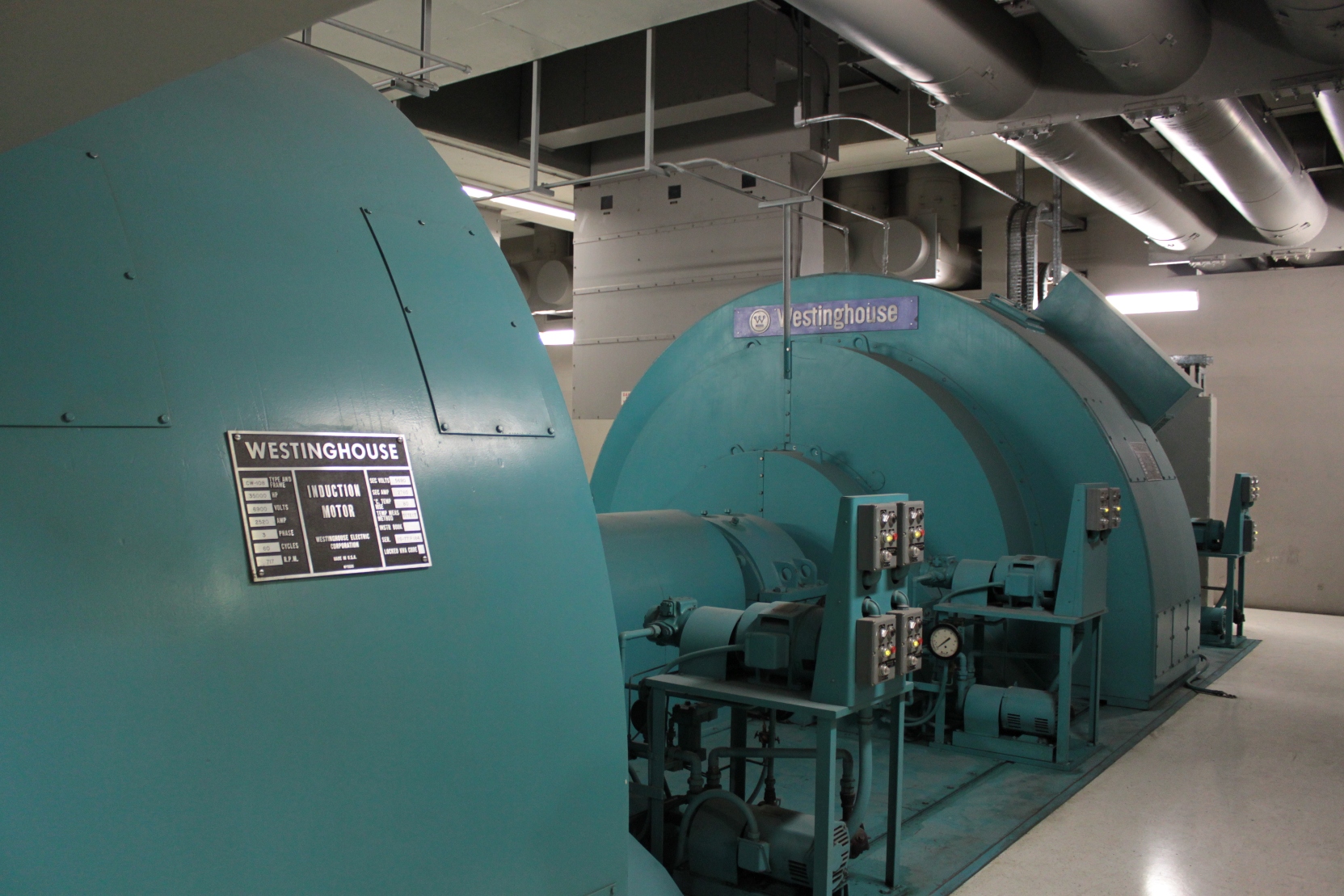
Okay, back to Edmonston, and it’s 14 pumps. When the pumps are started, they suck so much electricity that they can cause brown outs, so each motor is given a “soft-start”. The picture below is the Motor-Generator unit that starts up the pump. The pump’s motor is first connected to the Motor-Generator unit and accelerated up to speed and then synchronized to the power line before being switched over. If you want to know more about this procedure, click here. (See page 16, Section 3.4 if it doesn’t open up automatically to that page for you.) The pump motors are started in stages, one every 6 minutes.
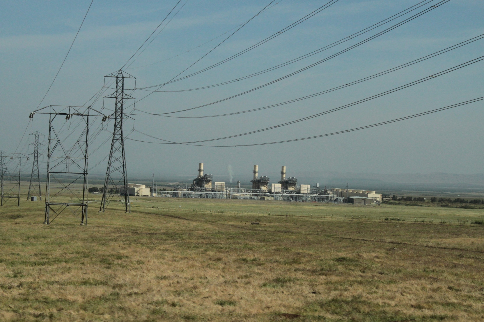
The pumps at Edmonston use the most electricity in the State Water Project system, accounting for 45% of the SWP’s power use, so it’s no surprise there’s a power generating station nearby.
The four of the pumps have recently been replaced with new Hitachi pumps that are more efficient. Not sure they are any smaller, though … You can learn more about the new pumps by clicking here, or by clicking here.
The facility was completed in 1972. Then-Governor Ronald Reagan was on hand to open the facility. (Historical pictures courtesy of Department of Water Resources).
Here are a few other pictures I took on the tour:
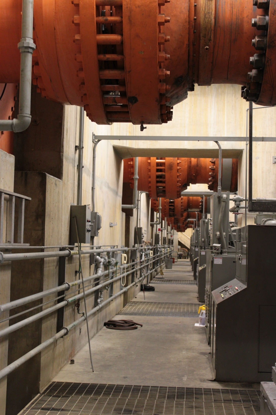
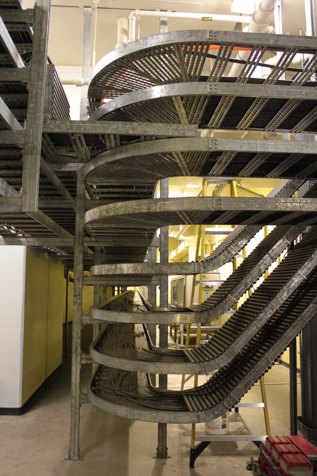
These are the cable trays that run the electrical wires around the facility.
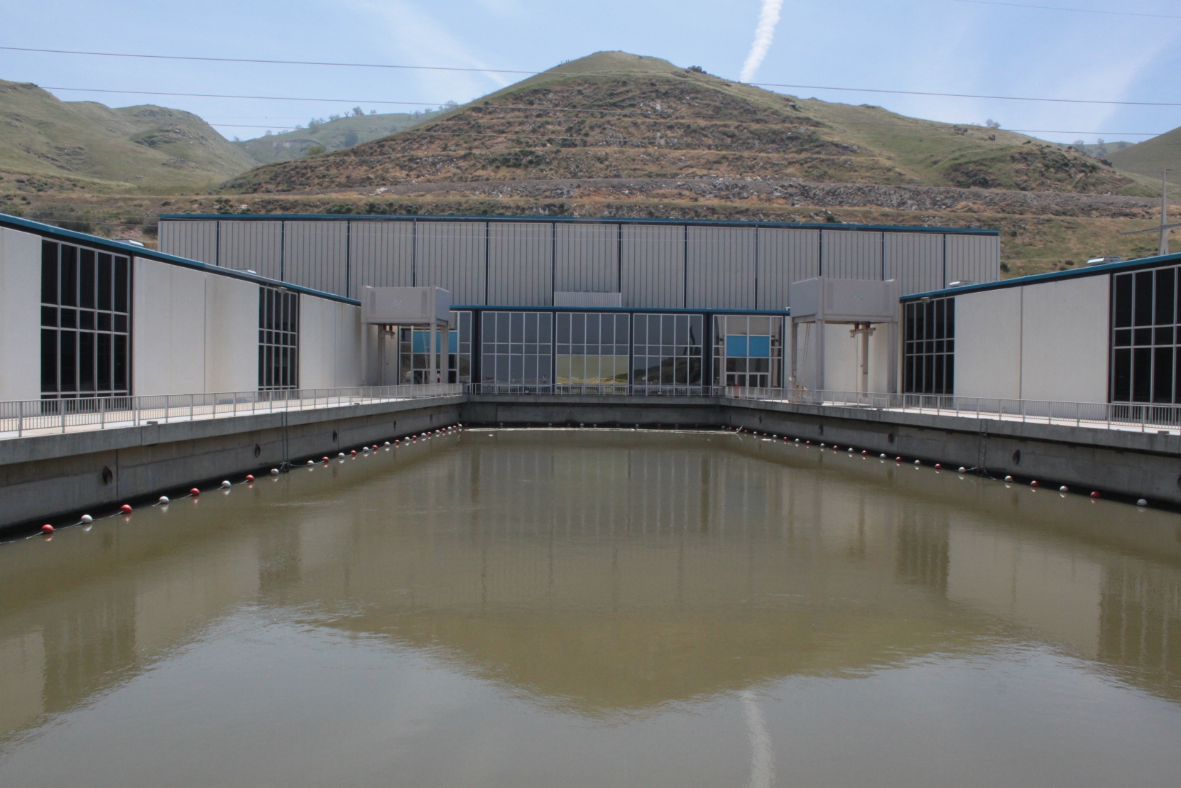
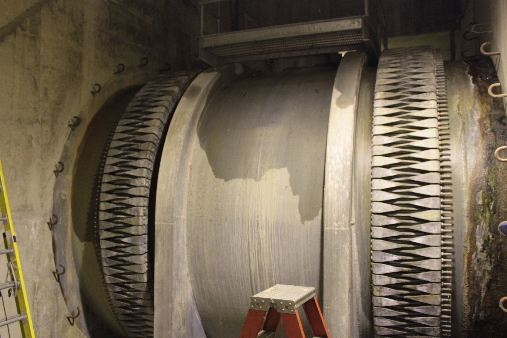
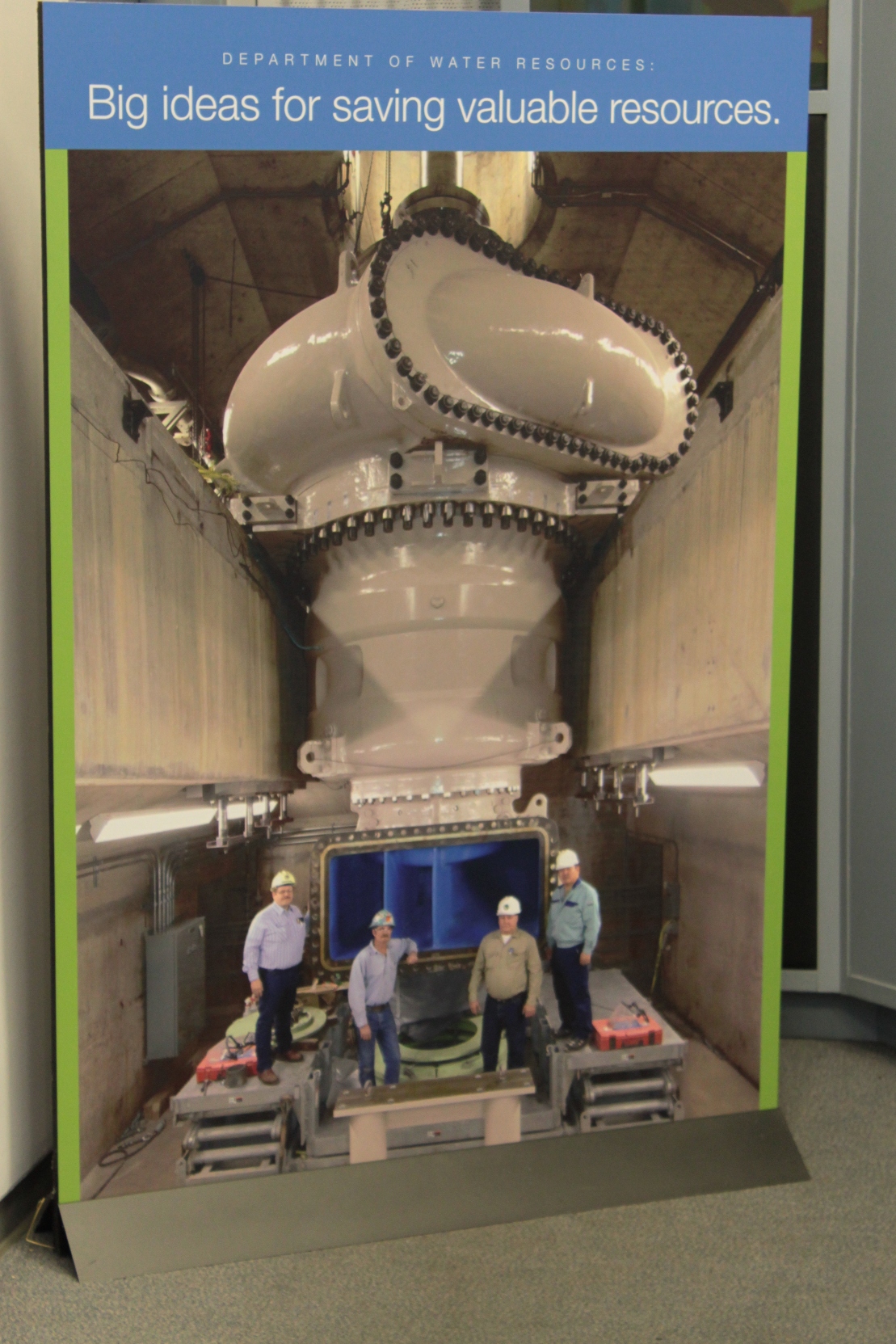
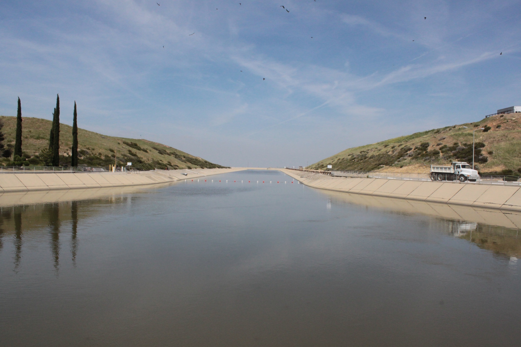
Here comes the water …
Note: The Edmonston Pumping Plant is located at the end of a private road and is not open to the public.
For more information on the Edmonston Pumping Plant and the California State Water Project:
- Check out this Popular Science magazine article from 1972 on the construction and opening of the State Water Project at Google books


Maven, you’ve outdone yourself on this one — spectacular!
In ’70 or ’71 I snuck in to the construction site. The base of the pipes were visible then. I was too far away to be able to accurately estimate the size, but I remember thinking that one could fit the cab of a semi inside each. Oh, if I had the film I shot four decades still available.
The common figure is that 18 percent of the State’s power is to move water around. I wonder how much of that is used by this one facility.
Thanks again, for your spectacular photographs.
Steve Ela
Yes, it’s some facility. Goes six floors down – guess I should have mentioned that in the post. It’s an amazing piece of infrastructure!
Thanks for the complement!
-Maven (Chris)
ACTUALLY, IT IS 12 FLOORS DOWN, ALL THE FLOORS ARE DOUBLES.
ps, I WORK THERE. TOTALLY AWESOME PLACE!!
Are you hiring? =P
No,are you?
I could use a job, too!
😛
I grew up on Harris Farms and the aqueduct was built 1-2 miles from where we lived. We used to ride our bikes down the side of it before the water was in it. Even then it was amazing to me. I was around 8-10 years old.I think about the construction work eveytime there is massive flooding somewhere in the USA and wonder why the country doesn’t build something similar to move flood waters from east to west and north to south
P.S. really good pictures. Thank You
Excellent Article! I cam across it doing some research on the Pumping station.
It actually uses 2% of all of California’s electricity per year Very impressive! I’m a bit of an infrastructure nerd.
Great photos of the pumping station. Where do I get the phone number for a group tour of the facility?
Thank you.
In 1972 electric power was not near as expensive as today. It seems that 2% of the electricity in California would we a large amount of money. Is there no way to use a tunnel boring machine and drill through the mountains instead of going over them.
Actually, they kept it close to the surface on purpose. The aqueduct crosses a few major earthquake faults, so in the event of an earthquake, it’s much easier to repair closer to the surface.
Thanks for stopping by!
Baldwin-Lima-Hamilton (BLH) was located in Eddystone, PA and built 7 of the pumps along with other very large equipment (they had been famous for steam locomotives). It would be surprising to current engineers the simplicity of the pump testing facilities used to design the pumps. I worked at BLH in 1970 when the “doors were being closed”. BLH had been acquired by a conglomerate that then sold off the different business lines. The pump business was sold to a European company. Thus, another large manufacturing facility was lost. Hard to imagine the pumps are still operating 40+ years later.